PROBLEM
Electric assemblies must fulfill strong safety regulations regarding creepage and clearance distances in order to prevent hazards caused by electric sparks. However, these distances depend on many complex aspects and without a software tool, a designer has to resort to manual measurements and rough approximations. This is not only time consuming, but also highly inaccurate and often causes expensive loops in the production pipeline.
SOLUTION
AutoCrear provides a robust and efficient software-based analysis of creepage and clearance. Based on over 5 years of research, it features novel state-of-the-art algorithms to handle the highly complex metrics of creepage and clearance paths and is capable of processing even large assemblies. This enables a designer to robustly detect and eliminate all safety violations in the early design stage and thus, significantly optimizes the production of electric assemblies.
AutoCrear is a standalone tool which combines the entire workflow of a creepage and clearance analysis in a single program:
- Applicable for every CAD system
- No external data preparation required
- Integrated high-performance 3D viewer
- Convenient workflow and session management
- Automatic generation of an analysis report
For more videos visit our tutorial section or our youtube channel.
WORKFLOW
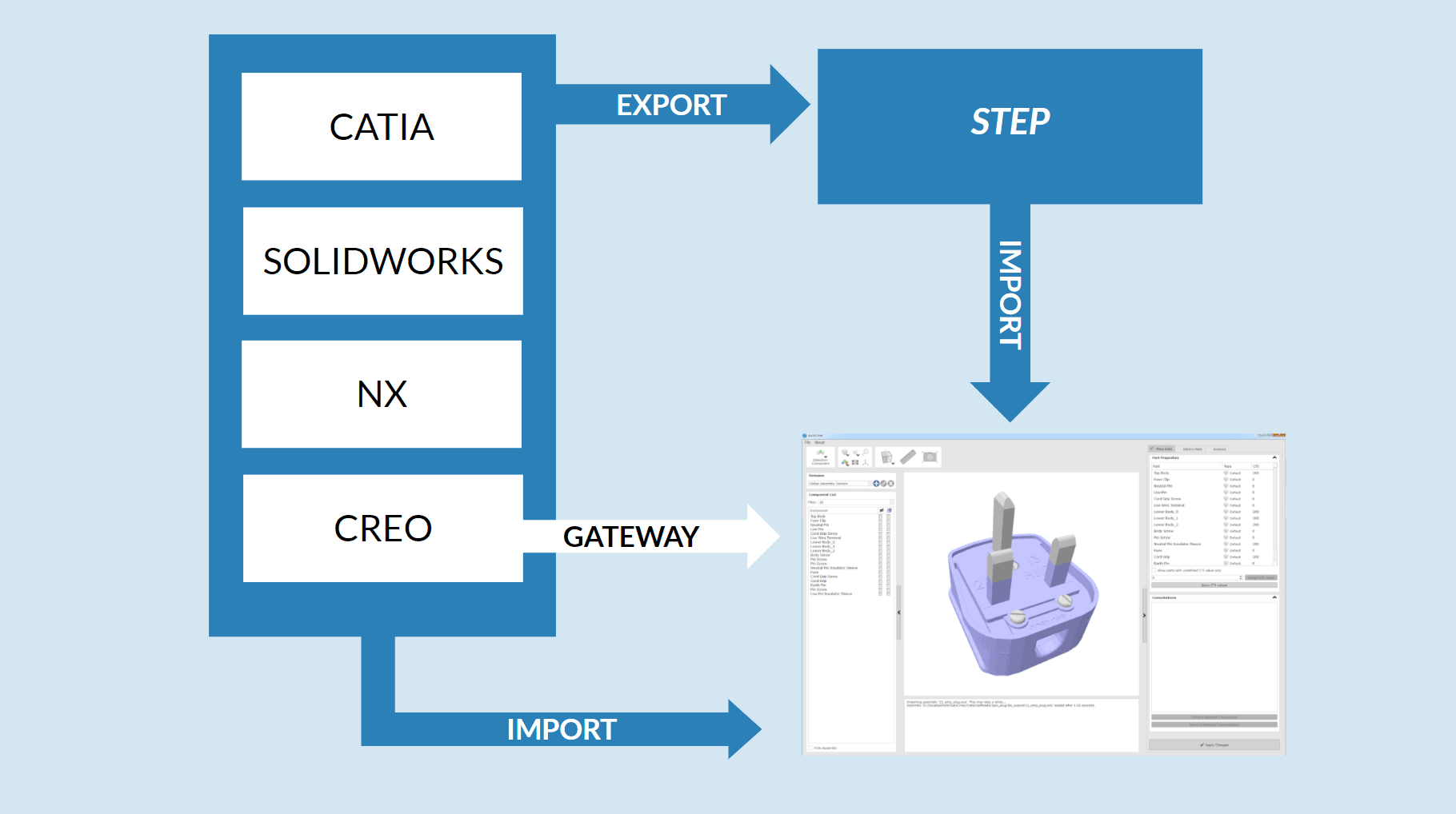
In the basic Version, AutoCrear can import STEP files. An interface extension allows for a direct import of all common native formats.
Electronic data can be directly imported in the format ODB++, whereas a clean 3D model of the PCB is automatically generated and the material- and network-information is automatically assigned to the data.
For Creo users, e-laborate Innovations offers free plug-ins, which allow to start an AutoCrear session directly from Creo. The current working assembly is thereby automatically imported.
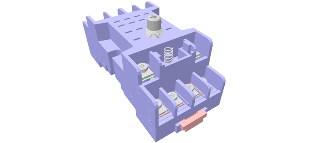
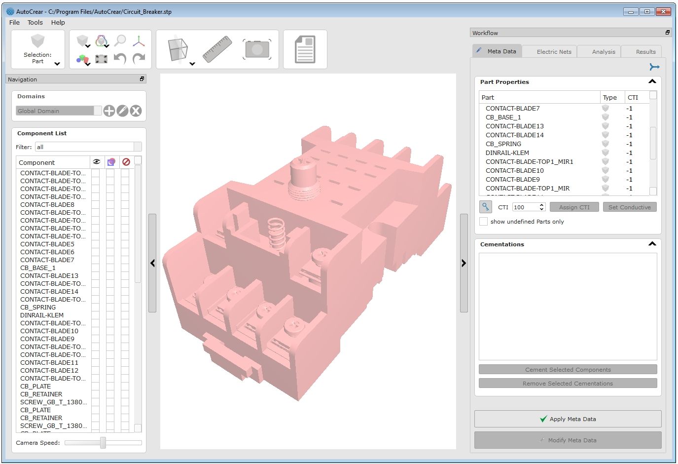
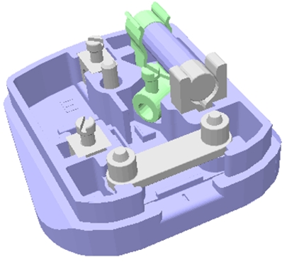
The CTI value is an essential material property for a creepage and clearance analysis. AutoCrear allows to set these values with a few mouse clicks for entire parts or individual surfaces. In the default color mode, the user gets immediate visual feedback of the specified material properties.
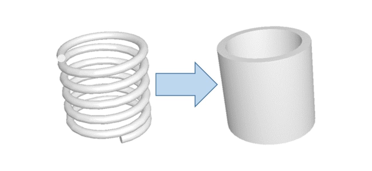
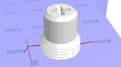
Some types of parts such as springs or screws have strong degree of freedom with respect to a rotation around their main axis which significantly influences an analysis. AutoCrear can automatically pre-process such parts in order to make the analysis more robust.
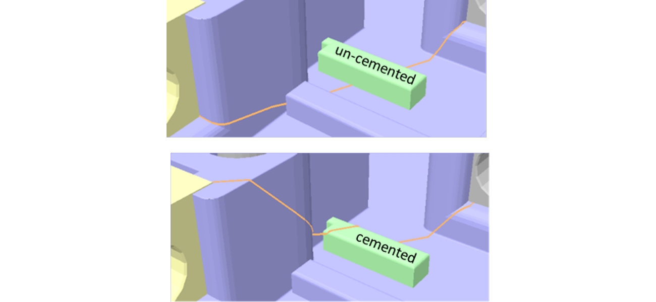
Whether or not two adjacent insulators are cemented or not has a significant influence on the analysis. In AutoCrear, cementations can be explicitly specified in order to automatically take care of this fact.
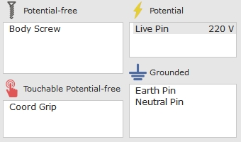
 Potential: the net is supplied with an electric potential. Such a net can act as source as well as target of a creepage or clearance path.
  Grounded: The net is explicitly grounded and can act as target of an analysis.
  Potential-free: The net is neither supplied with an electric potential nor is it grounded (e.g. screws). Such a net can act as intermediate source and foreshorten a path.
  Touchable: The net is actually potential free, but can be temporarily a grounded when a person touches it. Such net can act as targets of an analysis and as intermediate sources.
The analysis engine of AutoCrear must know which distances have to be fulfilled between the net pairs and which groove width should be applied for creepage. This information can be handed to the computation in two ways:
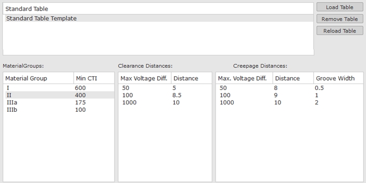
Using Standard Tables
The distance values are usually defined by industry standards and depend on the voltage difference, the used insulation class and the degree of pollution. AutoCrear offers the possibility to define and to apply such standard tables.
Custom Parameters
Alternatively, the distance values can be specified directly between each net pair. This allows to check for individual distances apart from any industry standard.
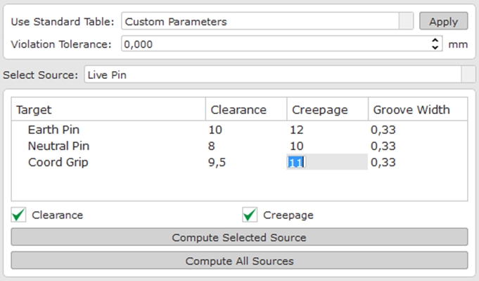
After the previous steps have been processed, an automatic creepage and/or clearance analysis can be started for a single source net or for all sources at once.
The time for a full analysis depends on the size of the assembly and can vary from a few seconds for small or moderate assemblies (< 10MB) up to a few hours for extremely huge assemblies (> 200 MB).
The computation considers all relevant aspects about creepage and clearance paths:
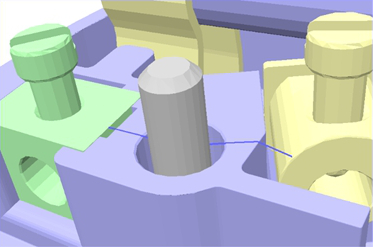
Creepage and clearance currents can take shortcuts through potential-free conductors (e.g screws). This aspect is automatically considered in AutoCrear.
According to industry regulations, the creepage is allowed to jump for a certain distance. This allows a creepage path to pass a groove if the groove width parameter is sufficient.
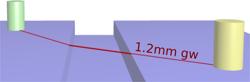
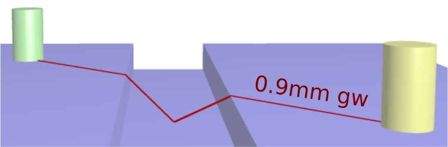
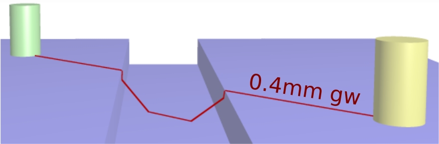
Example: creepage over a 1.0mm groove with different groove width parameters
The groove width parameter is not only applied to jump over a groove, but also to foreshorten a path at each possible occasion (e.g. non-convex edges). This aspect makes an exact creepage computation highly complex and is fully considered in AutoCrear.
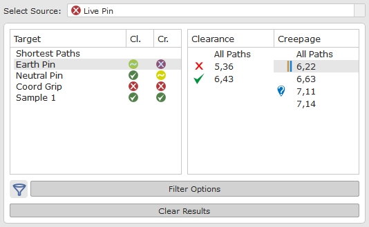
After the analysis, all paths between the net pairs which fall below the specified distance can be browsed and visualized.
Icons provide immediate visual feedback of the type of violation between each source/target net pairs:
 Major violation
 Minor violation
 No violation
Tags can be manually set for each path to explicitly confirm a violation ![]() ,
to overrule a violation
,
to overrule a violation ![]() or to set a question mark
or to set a question mark ![]() .
.
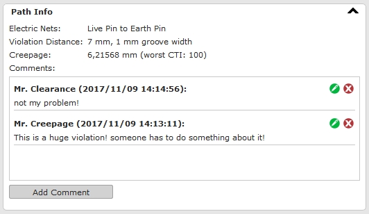
Comments can be added to a path which are automatically equipped with the date and user name. This allows for a communication about individual paths with other team members.
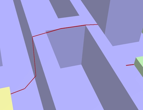
In many cases, paths are located deep inside the assembly, covered by several components. AutoCrear offers various features in order to quickly identify such paths. This includes moving the camera position to the start/end point of the path, setting a highlight around the path, automatically hiding components which are not involved in the path or activating a "Path Window".
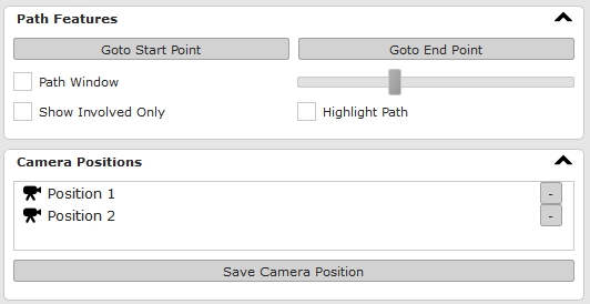
Camera positions can be permanently stored for each path in order to ease the repeated browsing of results. Also the stored camera positions are used for the automatic screenshot generation in the documentation feature.
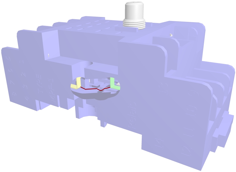
Example of a Path Window. A certain section around the displayed path is automatically cut out of the assembly to see through occluding components.
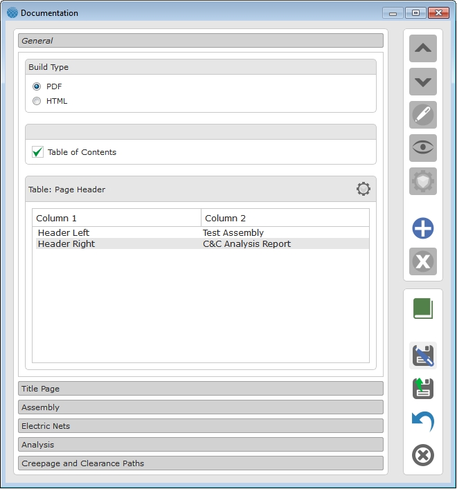
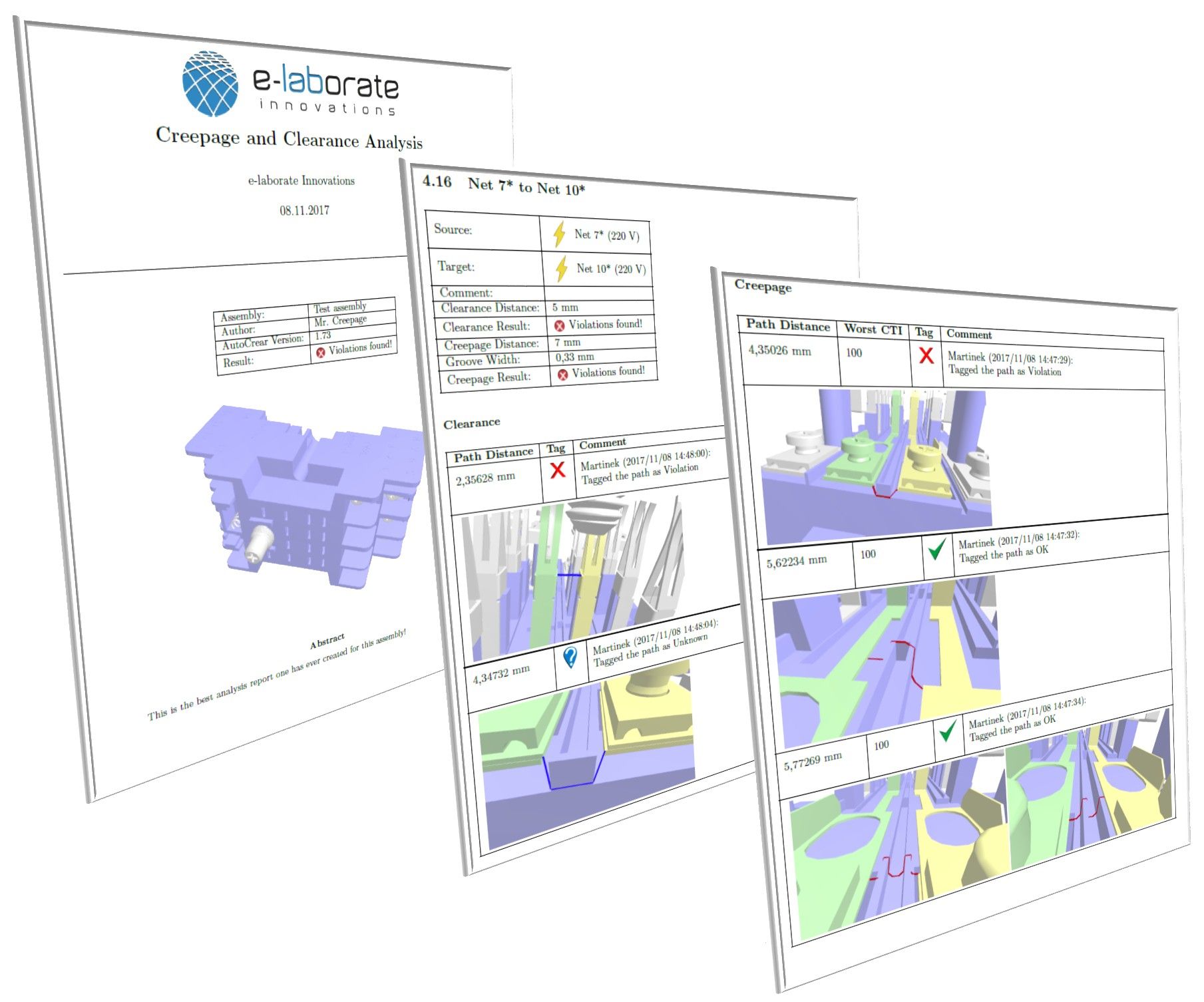
You can automatically create a customizable analysis report from the results, either as pdf or as html document. Beside custom items, the following contents can be automatically included:
- A title page including a company logo and general information about the assembly and the analysis
- A list of all components of the assembly including a screenshot and the specified meta data
- A list of all defined nets with screenshots and assigned properties
- An analysis summary listing the analysis parameters for each net pair along with the worst violation
- A detailed list of all paths between each net pair including screenshots (based on pre-defined camera positions) and the specified user comments and tags for each path
At any stage of the workflow, an AutoCrear Session file (.acs) can be saved. This file includes all required information to restore and continue the session at any time:
- The pre-processed geometry of the assembly
- The specified meta data
- The electric nets
- The analysis parameters
- The results
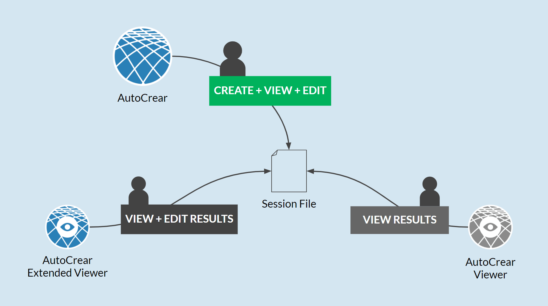
In the end, the session file can be seen as a digital 3D document of the analysis and can be loaded and viewed by any other team member using the free AutoCrear Viewer. The Original CAD data is not required as the geometry is stored in the session file. The cost-efficient AutoCrear Extended Viewer additionally allows to edit the results.
If the assembly is changed and re-loaded into a new AutoCrear Session, all the user input from a previous session can be automatically restored and must not be edited again.
Directly importing PCBs in the format ODB++ is an efficient way to perform a combined analyses of electronic and mechanic components.
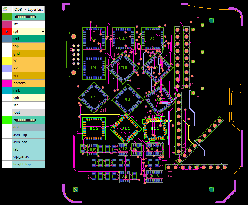
PCB in ODB++ format
2D Data of all PCB layers
Lossless exchange format, which can be exported from common ECAD systems
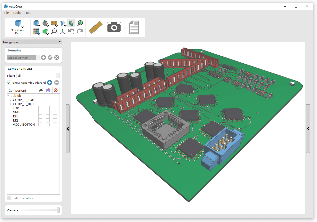
PCB in AutoCrear
Automatic generation of a 3D modell
All material properties, electric nets and net groups are imported from the ECAD data
BENEFITS
 Time
Time
Engineers of electric assemblies spent a significant amount of time to manually measure and document the creepage and clearance paths on their CAD design. Depending on the complexity, this can take several days / weeks. With AutoCrear, the process reduces to a few minutes / hours.
 Safety
Manual measurements are not only time consuming but also inaccurate. Violations concerning creepage and clearance distances can be missed, leading to unsafe product releases and possible recalls. AutoCrear avoids this worst-case scenario due to an exact computation of creepage and clearance paths.
 Quality
Compactness is often an important quality feature for electric assemblies. However, building electric nets closer together increases the risk of safety violations regarding creepage and clearance. As a result, engineers tend to add too much safety distance between nets. AutoCrear allows to design assemblies as compact as possible without violating the industry regulations.
 Costs
Costs
In any case, AutoCrear saves the costs an engineer has to spend on manual creepage/clearance measurements and documentations. This saves ~ 2,000 - 10,000 EUR per assembly. If a violation is missed by manual measurements, unnecessary production loops or even product recalls are the result. The costs for such a scenario can run into millions. AutoCrear provides an insurance against this worst-case.
PRODUCTS
| Feature | AutoCrear | AutoCrear Ext. Viewer | AutoCrear Viewer |
|---|---|---|---|
| Importing MCAD data |  |
- | - |
| Importing ECAD data | |
- | - |
| Loading session files | |
|
|
| Saving session files | |
|
- |
| 3D viewer | |
|
|
| Assigning meta data | |
- | - |
| Defining electric nets | |
- | - |
| Performing creepage and clearance computations | |
- | - |
| Display creepage and clearance paths | |
|
|
| Tagging, commenting, deleting paths | |
|
- |
| Automatic documentation features | |
|
- |
INTEGRATION OF AUTOCREAR INTO YOUR SYSTEM
AutoCrear can be purchased as a standalone tool that supports common CAD formats or as a plugin solution for PTC Creo. In addition to the software package we offer an individual integration of AutoCrear into your production pipeline combined with trainings. Furthermore, a clearance and creepage analysis as a service provides you a first introduction to our method. If you are interested in AutoCrear, please don't hesitate to contact us.
DOWNLOAD AUTOCREAR